Understanding Industrial Control Valves and their Types
Brian Craig
April 20, 2018
Control valves, also known as control nozzles, are essential products used in many industries. One of their most well-known applications is the oil and gas industry. Control valves are used to control operating conditions such as flow, temperature, pressure, and liquid levels. They accomplish this by opening the valves partially, or completely after receiving signals from controllers. In this post, we provide a brief introduction to this product for first-time customers.
The Basic Design of Control Valves
The general design of any control valve comprises three primary parts
- Body
- Actuator
- Positioner
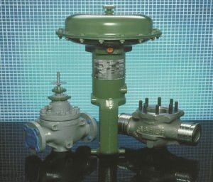
Control nozzles can be opened or closed via electrical, hydraulic, or pneumatic actuators. The positioners are used to open and close the actuator via pneumatic or electric signals. Depending on the type of control valve, these three components can have different designs.
Types of Control Valves
There are various types of control valves that can be used for industrial applications. The general types of valves used by various industrial sectors are given below.
- Angle Valves: This valve is operated manually, and is used to regulate fluid flow in pipes. The design consists of outlet openings, which are oriented to the inlet openings at right angles. Angle valves are sub-typed into cage-style and disk stack style valves.
- Globe Valves: This valve type is used to regulate pipeline flows. The design comprises a spherical body, with the two halves separated by a baffle. The valve has an opening where a movable disk or plug is placed to close the valve. Globe valves can be designed in single-port, three-way, port-guided, double-ported, high capacity cage-guided, and balanced-plug cage-style bodies.
- Rotary Valves: Rotary valves consist of transverse plugs, which rotate, thus allowing for flow regulation of gases or liquids. They are mainly used in steam and gas engines, and in industrial furnaces.
- Diaphragm Valves: Also known as membrane valves, diaphragm valves are designed with multiple ports. The diaphragm that closes the valve is located on top of a weir, or saddle. The design can include pneumatic, electric, hydraulic, or even manual actuators. Valves with two port bodies are known as 2/2-way valves, while bodies with three ports are called 3/2, or T valves. Bodies with more than three ports are called block valves.
- Air Operated Valves: As the name suggests, this valve type utilizes air pressure to produce linear or circular movements. The valve is supported by a piston or diaphragm. Air Operated valves can be designed as 2-way, 3-way, and 4-way valves. Sub-types include relay and pinch valves.
- Sliding Cylinder Valves: This type of valve is primarily used in applications involving steam engines. It helps control the amount of steam that goes into the engine. It is also used to control exhaust emissions. They slide from side to side, moving with other moving parts to control the steam and exhaust. Today, sliding cylinder valves are used in automobiles to control the intake of gas in engines.
- Angle Seat Piston Valves: These valves are controlled by pneumatic actuators. The design includes a piston actuator, which is used to provide linear movements to lift seals. Angle valves are primarily used in applications consisting of high flow rates and temperatures.
With the above information, first-time customers will be able to understand which valve will be suitable for their industrial applications. However, it is always a good idea to consult a valve supplier before making a decision.
Related Posts
- Causes & Solutions of Annoying Noise from Control Valves
- Understanding Industrial Control Valves and their Types
- All Important Questions on Control Valves Answered
- 3 Common Control Valve Maintenance Practices
- Know Everything About the Benefits, Applications, Types, and Automation of Control Valves
- How to Select the Right Control Valve for Your Process?
- Calibration of Control Valve Positioner: The Process Discussed
- Control Valve Actuators: Different Types and Failure Modes Discussed
- Calibration Guide for Fisher 3582 Pneumatic Positioner
- How to Do the Periodical Inspection and Maintenance of the Control Valve?
- Temperature Control Valve – Definition and Working Principle
- Reasons to Choose Remanufactured Instrumentation and Control Valves
- Fluid Flow Isolation Techniques for Pressure Instrumentation
- Single Acting vs. Double Acting Positioners: Pros and Cons
- Steam Boiler Drum Level Measurement A Comparison of Control System Technologies
- Furnace Flame Sensor Faults Everything You Need to Know for Safe Operation
- Comparison between Multi Valve Manifolds Block Valves and Bleed Valves
- Understanding Electrochemical Detection: Principles, Techniques and Environmental Application
- How Can Greenhouse Gas Emissions Be Reduced?
- Furnace Flame Sensor Faults Everything You Need to Know for Safe Operation
- Understanding Electrochemical Detection: Principles, Techniques and Environmental Application
- How Can Greenhouse Gas Emissions Be Reduced?
- Pneumatic Pressure Controllers: A Safe Choice for Hazardous Areas
- A Practical Guide to Vacuum Measurement and Operation
QUICK ENQUIRY
